
Close menu
Basic information
Smart Fastening
Smart Optics
Zmart is a representative organization of Kistler Remscheid (formerly Schatz) in Germany and AFS Advanced Connection Technology Research Institute in China. It was funded by Zwick China and has a German enterprise background. Its headquarters are located in Shanghai, and it has a joint laboratory for fastening connection technology with Huace Testing in Shanghai.

Close menu
Smart fastening
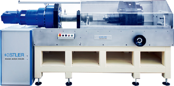
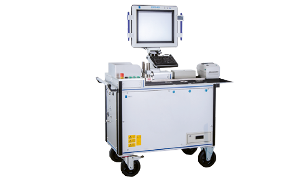
Friction coefficient testing machine
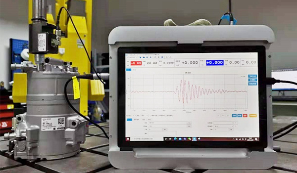
Ultrasonic axial force testing and analysis system
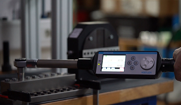
Thread Assembly Tool Testing System
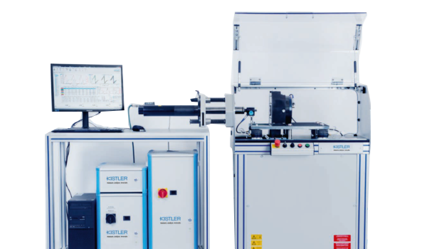
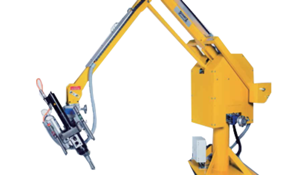
Simulated assembly test system
Close menu
Smart Optics
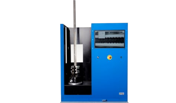
Fully automatic steel bar shape and size measuring instrument
Fully automatic bolt size measuring instrument

某车型后悬置与电驱动连接螺栓校核
Classification: Media News
Release Time:2026-05-13 16:54
某车型后悬置与电驱动连接螺栓校核
1螺栓连接布置
后悬置与电驱动连接螺栓布置如图,采用3个螺栓连接。

按照图示顺序,对应按照螺栓1,螺栓2,螺栓3的编号。

2螺栓连接载荷分析
后悬置与电驱动连接一般通过adams动力学仿真软件,或其他类似软件可以得出整体的外载荷,可以通过对螺栓孔施加coupling耦合,然后对悬置零件施加adams得出的外载荷,通过有限元提取出每个螺栓的载荷。
载荷工况按照GMW14116标准进行分析,载荷工况说明如下:
|
Load Case No. |
Powertrain Mounting System Analysis Load Cases |
'g' load on powertrain X |
'g' load on powertrain Y |
'g' load on powertrain Z |
Torque Acting on Powertrain |
Load Case Type |
|---|---|---|---|---|---|---|
|
1 |
Static design position (Under PT self weight ) |
|
|
-1 |
|
Typical |
|
2 |
Max forward engine torque** |
|
|
-1 |
See formula (1) below |
Typical |
|
3 |
Max reverse engine torque** |
|
|
-1 |
See formula (2) below |
Typical |
|
4 |
Max forward engine torque & forward acceleration** |
FWD: 0.5 |
|
-1 |
Load case 2 |
Typical |
|
5 |
Max forward engine torque & left cornering** |
|
1 |
-1 |
Load case 2 |
Typical |
|
6 |
Max forward engine torque & right cornering** |
|
-1 |
-1 |
Load case 2 |
Typical |
|
7 |
Max forward engine torque & bump** |
|
|
-3 |
Load case 2 |
Typical |
|
8 |
Max forward engine torque & rebound** |
|
1 |
|
Load case 2 |
Typical |
|
9 |
Max reverse engine torque & rearward acceleration** |
FWD: -0.6 |
|
-1 |
Load case 3 |
Typical |
|
10 |
8 KPH front bumper (- 11g) |
-11 |
|
-1 |
none |
Extreme |
|
11 |
8 KPH rear bumper (+ 11g) |
11 |
|
-1 |
none |
Extreme |
|
12 |
Vertical up loading |
|
|
4 |
none |
Extreme |
|
13 |
Vertical down loading |
|
|
-6 |
none |
Extreme |
|
14 |
Lateral left loading |
|
-3 |
-1 |
none |
Extreme |
|
15 |
Lateral right loading |
|
3 |
-1 |
none |
Extreme |
|
16 |
Vertical up & lateral left loading |
|
-3 |
4 |
none |
Extreme |
|
17 |
Vertical up & lateral right loading |
|
3 |
4 |
none |
Extreme |
|
18 |
Vertical down & lateral left loading |
|
-3 |
-6 |
none |
Extreme |
|
19 |
Vertical down & lateral right loading |
|
3 |
-6 |
none |
Extreme |
|
20 |
Up rough road |
|
|
2.5 |
none |
Typical |
|
21 |
Down rough road |
|
|
-4.5 |
none |
Typical |
|
22 |
Forward longitudinal loading |
-3 |
|
-1 |
none |
Typical |
|
23 |
Rearward longitudinal loading |
3 |
|
-1 |
none |
Typical |
|
24 |
Forward rockcycle / snap-clutch torque** |
|
|
-1 |
See formula (3) or (4) below |
Extreme |
|
25 |
Reverse rockcycle / snap-clutch torque** |
|
|
-1 |
See formula (3) or (4) below |
Extreme |
|
26 |
1 'g' static powertrain load |
|
|
-1 |
none |
Typical |
|
27 |
Forward partial torque**(5/8 Forward WOT) |
|
|
-1 |
As stated |
Typical |
|
28 |
Reverse partial torque**(5/8 Reverse WOT) |
|
|
-1 |
As stated |
Typical |
|
载荷工况编号 |
动力总成悬置系统分析载荷工况 |
动力总成'g'载荷 X |
动力总成'g'载荷 Y |
动力总成'g'载荷 Z |
作用于动力总成的扭矩 |
载荷工况类型 |
|---|---|---|---|---|---|---|
|
1 |
静态设计位置(动力总成自重下) |
|
|
-1 |
|
典型工况 |
|
2 |
前进发动机扭矩** |
|
|
-1 |
见下方公式(1) |
典型工况 |
|
3 |
倒挡发动机扭矩** |
|
|
-1 |
见下方公式(2) |
典型工况 |
|
4 |
前进发动机扭矩 & 前向加速** |
前驱: 0.5 |
|
-1 |
载荷工况2 |
典型工况 |
|
5 |
前进发动机扭矩 & 左转弯** |
|
1 |
-1 |
载荷工况2 |
典型工况 |
|
6 |
前进发动机扭矩 & 右转弯** |
|
-1 |
-1 |
载荷工况2 |
典型工况 |
|
7 |
前进发动机扭矩 & 颠簸** |
|
|
-3 |
载荷工况2 |
典型工况 |
|
8 |
前进发动机扭矩 & 回弹** |
|
1 |
|
载荷工况2 |
典型工况 |
|
9 |
倒挡发动机扭矩 & 后向加速** |
前驱: -0.6 |
|
-1 |
载荷工况3 |
典型工况 |
|
10 |
8公里/时前保险杠碰撞(-11g) |
-11 |
|
-1 |
无 |
极限工况 |
|
11 |
8公里/时后保险杠碰撞(+11g) |
11 |
|
-1 |
无 |
极限工况 |
|
12 |
垂直向上载荷 |
|
|
4 |
无 |
极限工况 |
|
13 |
垂直向下载荷 |
|
|
-6 |
无 |
极限工况 |
|
14 |
横向左侧载荷 |
|
-3 |
-1 |
无 |
极限工况 |
|
15 |
横向右侧载荷 |
|
3 |
-1 |
无 |
极限工况 |
|
16 |
垂直向上 & 横向左侧载荷 |
|
-3 |
4 |
无 |
极限工况 |
|
17 |
垂直向上 & 横向右侧载荷 |
|
3 |
4 |
无 |
极限工况 |
|
18 |
垂直向下 & 横向左侧载荷 |
|
-3 |
-6 |
无 |
极限工况 |
|
19 |
垂直向下 & 横向右侧载荷 |
|
3 |
-6 |
无 |
极限工况 |
|
20 |
崎岖路面向上 |
|
|
2.5 |
无 |
典型工况 |
|
21 |
崎岖路面向下 |
|
|
-4.5 |
无 |
典型工况 |
|
22 |
前向纵向载荷 |
-3 |
|
-1 |
无 |
典型工况 |
|
23 |
后向纵向载荷 |
3 |
|
-1 |
无 |
典型工况 |
|
24 |
前向急加速/离合器接合扭矩** |
|
|
-1 |
见下方公式(3)或(4) |
极限工况 |
|
25 |
倒挡急加速/离合器接合扭矩** |
|
|
-1 |
见下方公式(3)或(4) |
极限工况 |
|
26 |
1'g'静态动力总成载荷 |
|
|
-1 |
无 |
典型工况 |
|
27 |
前进部分扭矩**(5/8前进节气门全开) |
|
|
-1 |
按所述 |
典型工况 |
|
28 |
倒挡部分扭矩**(5/8倒挡节气门全开) |
|
|
-1 |
按所述 |
典型工况 |
注: 表格中带有 ** 标记的工况表示特殊载荷条件。

经过分析确定螺栓1所受的载荷,则后续计算以螺栓1为例进行校核,螺栓1能够满足载荷要求,其他更加没有问题。

切向载荷为21.3kN,轴向载荷为2.0kN。
去除极限工况以后,切向载荷为14.6kN,轴向载荷为1.4kN。
3螺栓连接计算软件SD Pro计算输入整理
根据相关的图纸,数模,材料及材料机械性能,可以整理出螺栓连接的相关输入,直接可以输入到螺栓计算软件中。


软件中按照初步设计的拧紧扭矩要求90Nm+90°进行计算。
4计算结果分析
输入完成后得到如图所示的接头示意图,通过该示意图可以检查确认输入的信息,尺寸是否有明显的错误异常。如果有异常,可以检查修改。

按照该拧紧工艺可以看到螺栓是过屈服拧紧的。螺栓按照90Nm+90°拧紧后预紧力为69.6kN-89.3kN,计算过屈服角度为67.5°-68.3°,由于实际拧紧时螺栓头下会有一定的磨损,假设按照0.1mm估算磨损量,相当于转动角度为24°,故理论过屈服角度可以设定过屈服的角度稍微大一些更加合理,更加符合实际情况,,当然,最终再通过试验进行该拧紧工艺的验证。


计算结果表明螺栓连接横向载荷抗滑移安全系数为0.55,低于1.0的要求。
由于本次计算采用载荷极限,故再次验证疲劳载荷工况的抗滑移安全系数。
螺栓头支撑面接触压力安全系数为1.05,在试验验证时候应特别关注头下压溃,同时,试验验证时需要特别关注轴力和静态扭矩的衰减,若出现轴力和静态扭矩衰减过大时,该项内容可重点关注并检查验证。


5疲劳载荷工况校核
由于极限工况载荷不能满足要求,螺栓连接预紧力不足,在极限工况载荷下会产生滑动。因此,按照疲劳工况重新校核。
输入如下:


此时按照结合面摩擦系数为0.18计算,螺栓连接抗滑移系数只有0.80仍然不能满足要求。


由于计算抗滑移系数低于1.0的要求,需要实测结合面摩擦系数
需要根据这个实际产品,通过实测结合面摩擦系数,可以看出都在0.226以上,比计算0.18要高。测试结果如下:
|
|
滑移力 |
轴力 |
滑移摩擦系数 |
|
kN |
kN |
μ |
|
|
1 |
12.60 |
50 |
0.252 |
|
2 |
11.30 |
50 |
0.226 |
|
3 |
11.60 |
50 |
0.232 |
|
4 |
11.30 |
50 |
0.226 |


输入结合面摩擦系数0.226,重新进行计算,抗滑移安全系数达到安全系数1.01满足1.0以上的要求。
因此,通过结合面实测摩擦系数可以安全抗滑移安全系数是满足要求,零件受载出现滑动的风险较低。
在台架和路试试验时也应特别关注该点的轴力和静态扭矩损失,旋转松动等情况,如果有较大的衰减,结合面滑移是重点检查的风险点。
6有限元补充分析
有限元也对该连接进行了简单分析


1、按照结合面摩擦系数0.226,螺栓头部摩擦系数0.09,零件结合面50%区域滑动,但螺栓头没有滑动
2、按照结合面摩擦系数0.18,螺栓头部摩擦系数0.09,零件结合面出现滑动,但螺栓头没有滑动
3、按照结合面摩擦系数0.13,螺栓头部摩擦系数0.09,零件结合面出现滑动,螺栓头50%接触面产生滑动
4、按照结合面摩擦系数0.10,螺栓头部摩擦系数0.09,有限元直接出现不收敛
从有限元简单分析趋势可以看出,在该连接模型中,螺栓头也会承受部分横向载荷,按照防松理论,通常螺栓头只要不出现滑动,螺栓连接就不会出现旋转松动,从这个意义上来说,该螺栓连接相对也是安全的。
VDI 2230标准中对于这种连接一般认为只有一个接触面来承受横向剪切力,最保守。实际有限元结果表明,螺栓头处是有或多或少的承受一部分横向载荷。
7螺栓连接分析结论
采用SD Pro螺栓计算软件计算结果表明,后悬置与电驱动连接螺栓,按照90Nm+90°拧紧工艺拧紧:
1、螺栓连接为过屈服拧紧
2、极限载荷作用下螺栓装配后预紧力不能满足抗滑移安全系数的要求
3、疲劳载荷作用下按照0.18结合面摩擦系数零件抗滑移安全系数0.80,低于1.0的要求。但通过实测结合面摩擦系数为0.226,此时抗滑移安全系数为1.01,满足安全系数1.0的要求
4、通过有限元分析也可以看出在0.18结合面摩擦系数下,尽管结合面之间出现了滑动,但螺栓头下仍然没有出现滑动,仍然具备防松性能。故根据实测结合面摩擦系数和有限元分析,初步认为该螺栓连接滑移的风险还是比较低
5、尽管实测和有限元分析表明,零件滑移风险较低,但是在装配试验时应加强轴力和拧紧扭矩衰减检查;如装配后出现较大轴力和扭矩衰减,可重点考虑和验证该因素
6、螺栓头下表面压溃安全系数只有1.05,在装配试验时也应加强轴力和拧紧扭矩衰减检查;如装配后出现较大轴力和扭矩衰减,可重点考虑和验证该因素。同时,在螺栓与铝合金零件进行连接时,建议采用GB 5789标准的加大法兰面螺栓
The Previous: 螺栓疲劳断裂:原因、影响因素与改进措施综述(详细螺栓疲劳资料)